Working Load Limit (WLL) - Grade 10
General: Tables specify max load for general chain dimension in grade 10 for use in slings.
| Chain | WLL t | |||||||
|---|---|---|---|---|---|---|---|---|
| Ø | Single | 2-leg & Basket | 3-4-leg | Endless | ||||
 |
 |
 |
 |
 |
 |
 |
 |
|
| mm | Straight | Choked | Basket | 0°-45° | 45°-60° | 0°-45° | 45°-60° | Choked |
| 6 | 1,4 | 1,12 | 2,8 | 2 | 1,4 | 3 | 2,12 | 2,24 |
| 8 | 2,5 | 2 | 5 | 3,55 | 2,5 | 5,3 | 3,75 | 4 |
| 10 | 4 | 3,15 | 8 | 5,6 | 4 | 8 | 6 | 6,3 |
| 13 | 6,7 | 5,3 | 13,4 | 9,5 | 6,7 | 14 | 10 | 10,6 |
| 16 | 10 | 8 | 20 | 14 | 10 | 21,2 | 15 | 16 |
| 19 | 14 | 11,2 | 28 | 20 | 14 | 30 | 21,2 | 22,4 |
| 22 | 19 | 15 | 38 | 26,5 | 19 | 40 | 28 | 30 |
| 26 | 26,5 | 21,2 | 53 | 37,5 | 26,5 | 56 | 40 | 42,5 |
| 32 | 40 | 31,5 | 80 | 56 | 40 | 85 | 60 | 63 |
| Factor(KL) | 1 | 0,8 | 2 | 1,4 | 1 | 2,1 | 1,5 | 1,6 |


Working Load Limit (WLL) - Grade 8
General: Tables specify max load for general chain dimension in grade 8 to for use in slings.
| Chain | WLL t | |||||||
|---|---|---|---|---|---|---|---|---|
| Ø | Single | 2-leg & Basket | 3-4-leg | Endless | ||||
 |
 |
 |
 |
 |
 |
 |
 |
|
| mm | Straight | Choked | Basket | 0°-45° | 45°-60° | 0°-45° | 45°-60° | Choked |
| 4 | 0,5 | 0,4 | 1 | 0,71 | 0,5 | 1,06 | 0,75 | 0,8 |
| 5 | 0,8 | 0,6 | 1,6 | 1,12 | 0,8 | 1,6 | 1,18 | 1,25 |
| 6 | 1,12 | 0,9 | 2,24 | 1,6 | 1,12 | 2,36 | 1,7 | 1,8 |
| 7 | 1,5 | 1,2 | 3 | 2,12 | 1,5 | 3,15 | 2,24 | 2,5 |
| 8 | 2 | 1,6 | 4 | 2,8 | 2 | 4,25 | 3 | 3,15 |
| 10 | 3,15 | 2,5 | 6,3 | 4,25 | 3,15 | 6,7 | 4,75 | 5 |
| 13 | 5,3 | 4,2 | 10,6 | 7,5 | 5,3 | 11,2 | 8 | 8,5 |
| 16 | 8 | 6,4 | 16 | 11,2 | 8 | 17 | 11,8 | 12,5 |
| 18 | 10 | 8 | 20 | 14 | 10 | 21,2 | 15 | 16 |
| 19 | 11,2 | 9 | 22,4 | 16 | 11,2 | 23,6 | 17 | 18 |
| 20 | 12,5 | 10 | 25 | 17 | 12,5 | 26,5 | 19 | 20 |
| 22 | 15 | 12 | 30 | 21,2 | 15 | 31,5 | 22,4 | 23,6 |
| 23 | 16 | 12,8 | 32 | 23,6 | 16 | 35,5 | 25 | 26,5 |
| 25 | 20 | 16 | 40 | 28 | 20 | 40 | 30 | 31,5 |
| 26 | 21,2 | 17 | 42,4 | 30 | 21,2 | 45 | 31,5 | 33,5 |
| 28 | 25 | 20 | 50 | 33,5 | 25 | 50 | 37,5 | 40 |
| 32 | 31,5 | 25,2 | 63 | 45 | 31,5 | 67 | 47,5 | 50 |
| 36 | 40 | 32 | 80 | 56 | 40 | 85 | 60 | 63 |
| 40 | 50 | 40 | 100 | 71 | 50 | 106 | 75 | 80 |
| 45 | 63 | 50 | 126 | 90 | 63 | 132 | 95 | 100 |
| Factor (KL) | 1 | 0,8 | 2 | 1,4 | 1 | 2,1 | 1,5 | 1,6 |


Working Load Limit (WLL) - Grade 12
| Chain | WLL t | |||||||
|---|---|---|---|---|---|---|---|---|
| Ø | Single | 2-leg | 3-4-leg | Endless | ||||
 |
 |
 |
 |
 |
 |
 |
 |
|
| mm | Straight | Choked | Basket | 0°-45° | 45°-60° | 0°-45° | 45°-60° | Choked |
| 7 | 2,36 | 1,9 | 4,72 | 3,35 | 2,36 | 5 | 3,55 | 3,75 |
| 8 | 3 | 2,36 | 6 | 4,25 | 3 | 6,3 | 4,5 | 4,75 |
| 10 | 5 | 4 | 10 | 7,1 | 5 | 10,6 | 7,5 | 8 |
| 13 | 8 | 6,3 | 16 | 11,2 | 8 | 17 | 11,8 | 12,5 |
| 16 | 12,5 | 10 | 25 | 17,5 | 12,5 | 26,5 | 19 | 20 |
| Factor (KL) | 1 | 0,8 | 2 | 1,4 | 1 | 2,1 | 1,5 | 1,6 |
Use in Adverse Environments
Temperatureaffects on working load limit (WLL)
Account should be taken to the maximum temperature that can be reached by the chain sling in service. This is difficult in practice but underestimation of the temperature should be avoided. The table below summarises the necessary de-rated working load limit due to temperature.
Chain slings in grade 8 and 10 will not be negatively affected by temperatures down to -40 °C which result in the fact that no reduction of the working load limit are needed. When chain slings are to be used in temperatures below -40 °C CERTEX should be consulted.
The use of a chain sling in grade 8 and 10 within the permissible temperatures ranges given in the table does not require any permanent reduction in working load limit. Working load limit are valid again when the chain sling is used in normal temperature again. If the chain sling reach temperatures that highly exceed the maximal allowed according to the table it should be discard or be returned to CERTEX for measure.
| Grade | Allowed load expressed in % of working load limit (WLL) | |||
|---|---|---|---|---|
| Temperature (t) °C | ||||
| -40 - 200 | 201 - 300 | 301 - 400 | 401- 475 | |
| 8 | 100 | 90 | 75 | Not allowed |
| 10 | 100 | Not allowed | Not allowed | Not allowed |
| 10+ | 100 | 100 | 100* | Not allowed |
| *Grade 10+ only allowed up t=380°C | ||||
Acidic conditions
Chain slings in grade 8 and 10 should not be used either immersed in acidic solutions or exposed to acid fumes.
Chain slings should, for the same reason, not be warm-galvanized or exposed to electroytic finish without permisson from CERTEX.
Chemical affects
CERTEX should be consulted in case the slings is to be exposed to chemicals combined with high temperature.
Safe Use
Preparation
Before starting the lift, it should be ensured that the load is free to move and is not bolted down or otherwise obstructed.
Packing may be required where a chain comes into contact with a load in order to protect either the chain or the load or both, since sharp corners of hard material may bend or damage the chain or, conversely, the chain may damage the load because of high contact pressure. Corner protection should be used to prevent such damage.
In order to prevent dangerous swaying of the load and to position it for loading, a tag line is recommended.
When loads are accellerated or delcelerated suddenly, dynamic forces occur which increase the stresses in the chain. Such situations, which should be avoided, arise from snatch or shock loading eg. from not taking up the slack chain before starting to lift, or because of the shock from falling load being stopped.
Mass of the load
It is essential that the mass of the load to be lifted is known.
Gravity
It is assumed that the attatchment point of the hook is directly above the centre of gravity of the load.
The position of the center of gravity of the load in relation to all attatchment points for the chain sling should be established. To lift the load without rotation or overturning following conditions should be met:
a) For single-leg and single endless slings the attatchment point should be vertically above the centre of gravity.
b) For 2-leg slings the attatchment points should either side of and above the centre of gravity.
c) For 3- and 4-leg slings the attatchment points distributed in plan around the centre of gravity. It is preferable that the distribution should be equal and that the attatchment points are above the centre of gravity.
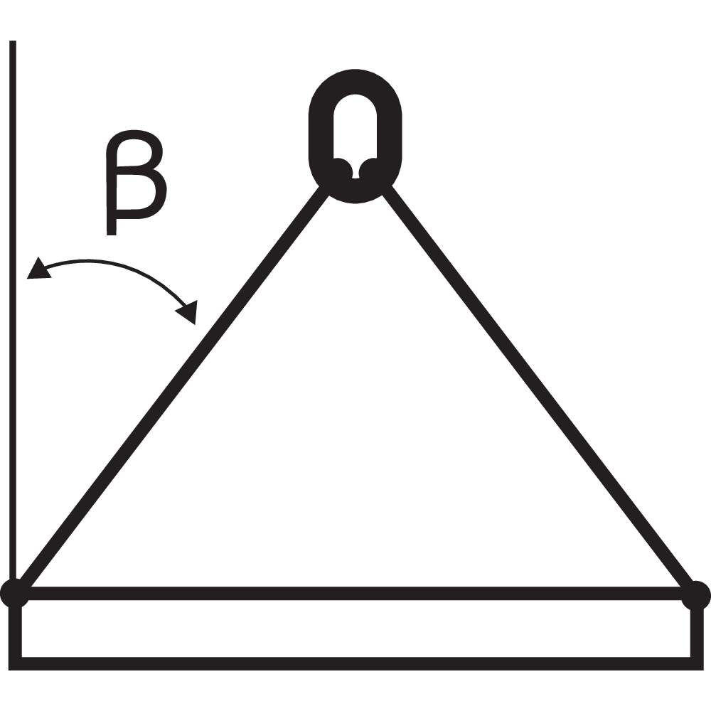
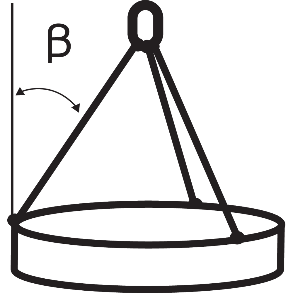
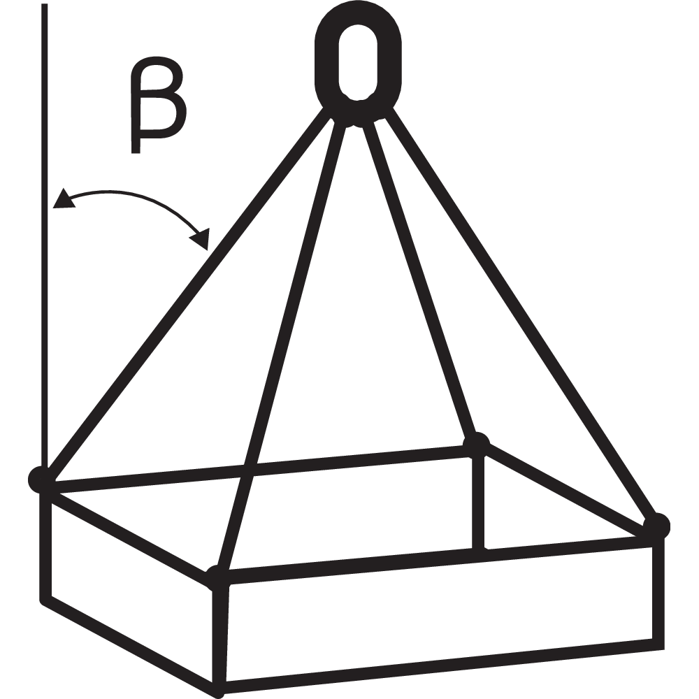
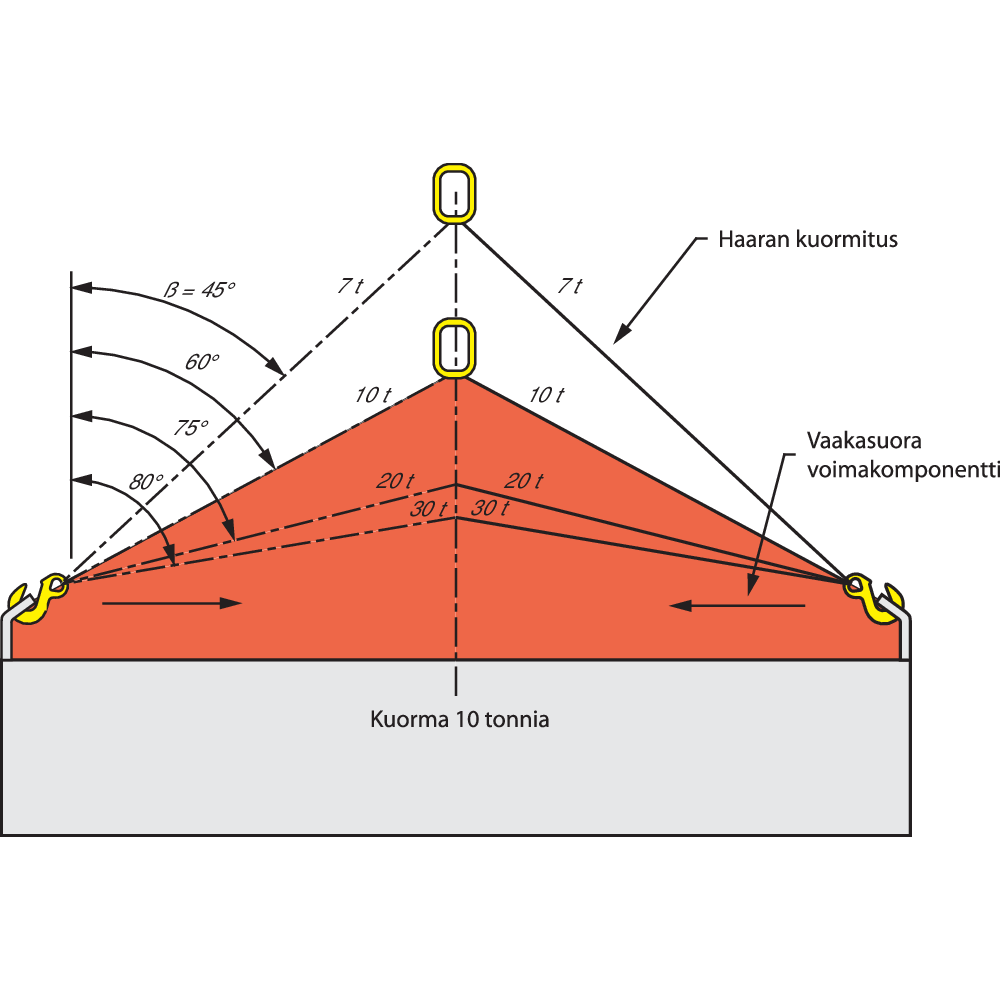
When using 2-, 3- and 4-leg slings the attatchment points and sling configuration should be selected to achive angle between the slings legs and the vertical within the range marked on the sling. Preferably all angle to the vertical angle (angle ß) should be equal. Angles to the vertical of less than 15° should be avoided if possible as they present a significantly greater risk of load imbalance.
All multi-leg slings exert a horizontal component of force (see figure) which increases as the angle between the sling legs is increased. If the chain is pulled through an eye, hook or other type of attatchment tool, eg. chainsling for barrel the horizontal component of force are a lot higher. The result of this is that the vertical angle for the legs in this case not should exeed 30°. Care should always be taken to ensure that the load to be moved is able to resist the horizontal component of force, without being damaged.
Method of connection
A chain sling is usually attached to the load and the lifting machine by means of terminal fittings such as hooks and links. Chains should be without twists or knots.
The lifting point should be seated well down in a hook, never on the point or wedged in the opening. The hook should be free to incline in any direction so as to avoid bending. For the same reason, the master link should be free to incline in any
direction on the hook to which it is fitted.
The chain may be passed under or through the load to form a choke hitch or basket hitch. Where it is necessary, due to the danger of the load tilting, to use more than one chain sling leg in a basket hitch, this should preferably be done in conjunction with a lifting beam.
When a chain sling is used in a choke hitch, the chain should be allowed to assume its natural angle and should not be hammered down.
Chain slings may be attached to the load in several ways:
Straight leg
In this case lower terminals are connected directly to the attachment points. Selection of hooks and attachment points should be such that the load is carried in the seat of the hook and tip loading of the hook is avoided. In the case of multi-leg chain slings hook tips should point outwards unless the hooks are specifically designed to be used otherwise.
Choke hitch
In this case chain sling legs are passed through or under the load and the lower terminal back hooked or reeved onto the chain. This method can, therefore, be used where no suitable attachment points are available and has the additional advantage that the chain sling legs tend to bind the load together.
Where choke hitch is employed the working load limit (WLL) of the chain sling should be no more than 80 % of that marked.
Basket hitch
The chain sling is passed through or under the load, the lower terminals are connected directly to the master link or to the hook of the lifting machine. Generally this method requires two or more chain sling legs and should not be used for lifting loads which are not held together. Where the load geometry permits, a single leg chain sling can be used provided that the chain sling passes through the load directly above the centre of gravity of the load.
Wrap and choke or wrap and basket hitch
These methods are adaptations of choke hitch and basket hitch, designed to provide extra security of loose bundles and involve taking an extra loop of chain completely around the load.
If two or more chain sling legs are used in a choke hitch or a wrap and choke hitch care should be taken:
a) if it is important to avoid imparting a torque to the load, to align the chokes; or
b) if it is important to avoid the load rolling or moving laterally when first lifted, to ensure that at least one leg passes either side of the load.
Packing may be required where a chain comes into contact with a load in order to protect either the chain or the load or both, since sharp corners of hard material may bend or damage the chain links or, conversely, the chain may damage the load because of high contact pressure. Packing, such as wooden blocks, may be used to prevent such damage.
In order to prevent dangerous swaying of the load and to position it for loading, a tag line is recommended.
When loads are accelerated or decelerated suddenly, high dynamic forces occur which increase the stresses in the chain. Such situations, which should be avoided, arise from snatch or shock loading e.g. from not taking up the slack chain before starting to lift or by the impact of arresting falling loads.
Symmetry of loading
Working load limits (WLL) for chains slings of different dimensions and configurations have been determined on the basis that the loading of the chain sling is symmetrical.This means that when the load is lifted the chain sling legs are symmetrically disposed in plan and subtend the same angles to the vertical.
In the case of three leg chain slings, if the legs are not symmetrically disposed in plan the greatest tension will be in the leg where the sum of the plan angles to the adjacent legs is greatest. The same effect will occur in 4 leg chain slings except that the rigidity of the load should also be taken into account, with a rigid load the majority of the mass may be taken by only three or even two legs with the remaining leg or legs serving only to balance the load.
In the case of 2-, 3- and 4- leg chain slings, if the legs subtend different angles to the vertical the greatest tension will be in the leg with the smallest angle to the vertical. In the extreme case, if one leg is vertical, it will carry all the load.
If there is both a lack of symmetry in plan and unequal angles to the vertical the two effects will combine and may either be cumulative or tend to negate each other. The loading can be assumed to be symmetric if all of the following conditions are satisfied and the load is less than 80 % of marked WLL:
a) chain sling leg angles to the vertical are all not less than 15°; and
b) chain sling leg angles to the vertical are all within 15° to each other; and
c) in the case of three- and four-leg chain slings, the plan angles are within 15° of each other.
If all of the above parameters are not satisfied then the loading should be considered as asymmetric and the lift referred to a competent person to establish the safe rating for the chain sling. Alternatively, in the case of asymmetric loading, the chain sling should be rated at half the marked WLL.
If the load tends to tilt, it should be lowered and the attachments changed. This can be accomplished by re-positioning the attachment points or by using compatible shortening devices in one or more of the legs. Such shortening devices should be used in accordance with CERTEX's instructions.
Safety of lift
Hands and other parts of the body should be kept away from the chain to prevent injury as the slack is taken up. When ready to lift, the slack should be taken up until the chain is taut. The load should be raised slightly and a check made that it is secure and assumes the position intended. Lifting personnel must be aware of the risks for swinging and tilting loads. This is especially important with basket or other loose hitches where friction retains the load.
Multi-legs chain slings with less than the full number of legs in use
As a general principle, chain slings should be used only for the purpose for which they have been designed. In practice, however, occasions may arise when a lift needs to be made using a smaller number of legs than the number of legs in the chain sling. In such cases the WLL should be reduced from that marked on the chain sling by applying the relevant factor given in table below.
Legs that are not in use should be hooked back to reduce the risk of such legs swinging freely, or snagging when the load is moved.
Working load limit (WLL) factors
| Types of chain sling | Number of legs used | Factor to apply to marked WLL |
|---|---|---|
| 2-leg | 1 | 1/2 |
| 3- and 4-leg | 2 | 2/3 |
| 3- and 4-leg | 1 | 1/3 |
Working load limit (WLL)
Taking into consideration the recommendations and the cumulative effects of de-rating, the method of slinging should be
decided and a suitable chain sling or selected so that the mass to be lifted does not exceed the WLL.
Landing the load
The landing site should be prepared. It should be ensured that the ground or floor is of adequate strength to take the oad taking account of any voids, ducts, pipes etc. which may be damaged or collapse. It should also be ensured that there is adequate access to the site and that it is clear of any unnecessary obstacles and people. It is preferable to use timber bearers or similar material to avoid trapping the sling or to protect the floor or load or to ensure the stability of the load when landed.
The load should be landed carefully ensuring that hands and feet are kept clear. Care should be taken to avoid trapping the wire rope sling beneath the load as this may damage it. Before allowing the rope to become slack, the load should be checked to ensure that it is properly supported and stable. This is especially important when several loose objectsare in basket hitch and choke hitch.
When the load is safely landed the wire rope sling should be carefully removed to avoid damage or snagging or cause the load to topple over. The load should not be rolled off the sling as this may damage the sling.
Storage of chain slings
When not in use wire rope slings should normally be kept on a properly designed rack. They should not be left lying on the ground where they may be damaged.
If the wire rope slings are to be left suspended from a crane hook, the sling hooks should be engaged in an upper link to reduce the risk of sling legs swinging freely or snagging.
If it is likely that wire rope slings will be out of use for some time they should be cleaned, dried and protected from corrosion, e.g. lightly oiled.


Before First Use
Before first use of the chain sling should be ensured that:
a) the sling is precisely as ordered;
b) the manufacturer's certificate is to hand;
c) the identification and working load limit marking on the sling corresond to the information on the certificate;
d) full details of the sling are recorded in a register of slings;
e) the actual use is to be as intended.
Hazardous Conditions
Particulary hazardous conditions including offchore actvities, the lifing of a person and lifting of potentially dangerous loads such as molten metals, corrosive materials or fissile materials. In such cases the degree of hazard should be assessed by a competent person and the working load limit adjusted accordingly.
Dimensioning of Chain Slings
Calculation of working load limit (WLL) for chain slings
When exact information about weight, lifting angle and positon of center of gravity exist, you're allowed to calculate the working load limit as followed:
2-leg sling
WLL (ton) = 2 x WLL for single leg sling x cos ß.
3-4-leg sling
WLL (ton) = 3 x WLL for single leg sling x cos ß.
Note: If the load is well divided on all 4 legs in a sling the following formula can be used in exeptional case:
WLL (ton) = 4 x WLL for single leg sling x cos ß.
ß = the legs angle against the vertical surface.
Marking
Slings are provided with a markingplate with manufacture's identifying mark, working load limit (WLL), length, date of manufacture and CE-marking.
![Markplate_s[new]_225mm](/sites/certex-fi/techdoc_import/Technical%20information%20general/CHAIN%20-%20LIFTING%20PRODUCTS/OLD_Technical%20information/Chain%20slings/Technical%20description/10565/image-thumb__10565__general-base/markplate_s-new-_225mm.d33a0ab6.png)
![Markplate_s[new]_225mm](/sites/certex-fi/techdoc_import/Technical%20information%20general/CHAIN%20-%20LIFTING%20PRODUCTS/OLD_Technical%20information/Chain%20slings/Technical%20description/10565/image-thumb__10565__general-thumb/markplate_s-new-_225mm.cea3d09b.png)
![Markplate_s[new]_225mm](/sites/certex-fi/techdoc_import/Technical%20information%20general/CHAIN%20-%20LIFTING%20PRODUCTS/OLD_Technical%20information/Chain%20slings/Technical%20description/10565/image-thumb__10565__general-base/markplate_s-new-_225mm.d33a0ab6.png)
Chain Slings
Tolerance of length
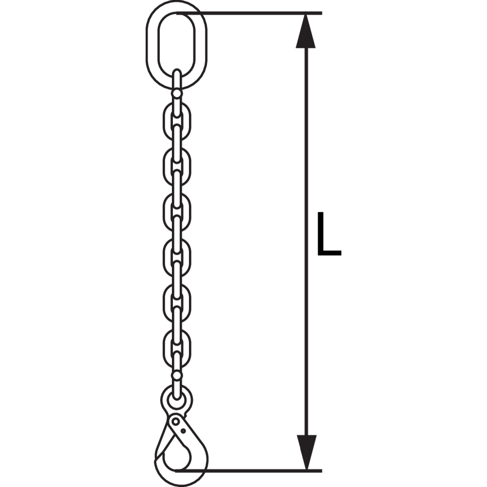
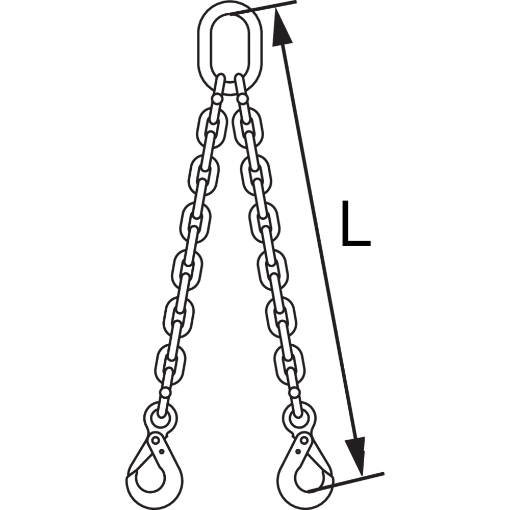
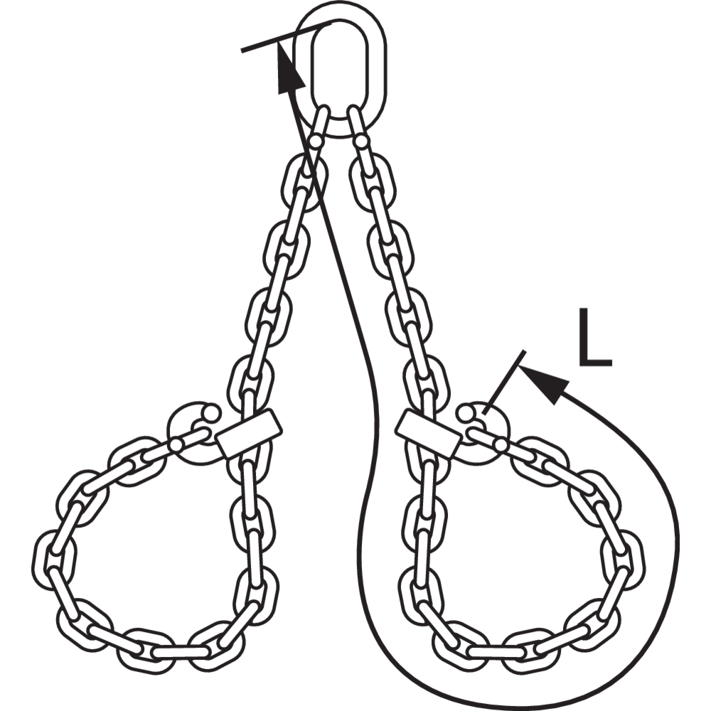
The length (L) shall be measured between the "bearing points" or the perimeter for endless slings.
The length on each leg shall be nominal length with a tolerance of -0/+2 chain link lengths.
The difference in length (usally the same for all legs) between the shortest and longest leg in a mulit-leg sling, assembled with connecting links, shall not exceed 10 mm if the sling is 2 m or less, for longer slings 5 mm/m is current.


Multi Leg Slings
The working load limit of any master link should be at least equal to that of the sling. The working load limit of any intermediate link fitted to a 3-leg or 4-leg sling should be at least equal to 1,6 times the WLL of the current chain.
WARNING! If the sling is to be used in an anticipated lift with a lifting angle less then (ß) 45° and with a higher working load limit than usual, it should be specified at time of order.


Repair
Any replacement component or part of the chain sling should be in accordance with the appropriate European Standard for that component or part.
With Grade 8 or Grade 4 chain slings, if any chain link within the leg of a chain sling is required to be replaced then the whole of the chain within that leg should be renewed.
The repair of chain in a welded chain slings should only be carried out by CERTEX using a resistance butt or flash butt welding process.
Components that are cracked, visibly distorted or twisted, severely corroded or have deposits which cannot be removed should be discarded and replaced.
Minor damage such as nicks and gouges may be removed by careful grinding or filing. The surface should blend smoothly into the adjacent material without abrupt change of section. The complete removal of the damage should not reduce the thickness of the section at that point to less than the manufacturers specified minimum dimensions or by more than 10 % of nominal thickness of the section.
In the case of chain slings on which repair work has involved welding, each repaired chain sling should be proof-tested following heat treatment using a force equivalent to twice the working load limit and thoroughly examined before it is returned to use. However, where repair is carried out by inserting a mechanically assembled component, proof-testing is not required providing that the component has already been tested by CERTEX in accordance with the relevant European standard.
Inspection
A thorough examination should be carried out of a competent person at intervals not exceeding twelve months. This interval should be
less where deemed necessary in the light of service conditions.
Records of such examinations should be maintained.
Chains slings should be thoroughly cleaned so as to be free from oil, dirt and rust prior to examination. Any cleaning method which does not damage the parent metal is acceptable. Methods to avoid are those using acids, overheating, removal of metal or movement of metal which may cover cracks or surface defects.
Adequate lighting should be provided and the chain sling should be examined throughout its length to detect any evidence of wear, distortion or external damage.
Examination
During service, chain sling are subjected to conditions that effect their safety. It is necessary, therefore, to ensure, as far as is reasonably practicable, that the sling is safe for continued use.
If the tag or label identifying the chain sling and its working load limit becomes detached and the necessary information is not marked on the master link, or by some other means, the chain sling should be withdrawn from service.
The sling should be withdrawn from service and reffered to a competent person for thorough examination if any of the following is observed before each use:
a) Illegible sling markings, i.e. sling identification and/or working load limit.
b) Upper or lower terminal fitting has deformed.
c) The chain has been overloaded. If the chain slings have extended, if free rotation between the links are missing or if there is a noticable difference in length between legs in a multi-leg sling, the reason can be that the chain has been overloaded.
d) Wear by contact with other objects usally occurs on the outside of the straight portions of the links where it is easyly seen and measured. Wear between adjoining links is hidden. The chain should be slack and adjoining links rotated to expose the inner end of each link. Inter-link wear (in the bearing points) is tolerated until the mean value of two maesured values 90° against each other has been reduced to 90% of the nominal diameter.
e) Cuts, nicks, gouges, cracks, excessive corrosion, heat discoloration, bent or distorted links or any other defects.
f) Signs of "opening out" of hooks, i.e. any noticeable increase in the throat openings or any other form of distortion in the lower terminal.
The increase in throat opening should not exceed 10 % of the nominal value or be such as to allow the safety latch, if fitted, to become disengaged.
![Markplate_s[new]_225mm](/sites/certex-fi/techdoc_import/Technical%20information%20general/CHAIN%20-%20LIFTING%20PRODUCTS/OLD_Technical%20information/Chain%20slings/Technical%20description/10565/image-thumb__10565__product-large/markplate_s-new-_225mm.c1d75ad5.png)
